Event Table
The Event Table enables to trigger action with specified Output based on events from selected Input. Event Table tab is common to all devices
Inputs:
- Acquisition and Idle events - Time, signal level, digital input state
- Events from Control module - Auxiliary signal level
- System events - Begin and end of sequence, acquisition etc.
Outputs:
- Digital Output control - DataApex A/D Converters
- Acquisition and Sequence control commands (Stop, Abort, Skip Vial, etc.).
- Run program - Launching an external program, with/without start parameters. Basic set of external tools is supplied with Clarity.
- None - Nothing will happen, suitable for development and testing of the method.
Each row in the table represents an independent event. When several events controlling the same output collide, the subsequent event masks the preceding one. When two events occur simultaneously, the event listed as last in the Event Table prevails.
Some events occurs in Running or Idle state only, these are coined with Run or Idle words in the event name.
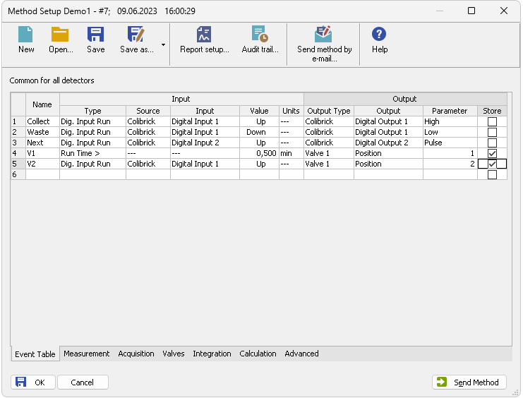
Method Setup - Event table
Individual lines or the entire table of events may be erased by right clicking the mouse on the available context menu above the table and using Delete Row or Delete All Rows commands. When a line becomes invalid, it will be highlighted with red background. Such row may be edited and must be repaired prior to saving the method. It is possible to select and copy the whole rows, paste them in the table and modify them. This is useful for creating sets of similar events.
Name
Arbitrary name to describe the event.
Input
The set of columns describing the Input that will trigger the action specified in Output columns.
Sets the type of the input. Available options are shown in the Tab "List of events available in the Event Table":
List of events available in the Event Table
| Name of the event | Condition on when the event is triggered |
|---|---|
| Run Time > | Duration of acquisition (Instrument in Running state) exceeds adjusted value (reset by every start of acquisition). |
| Input Run > | Measured quantity (e.g. input voltage or AU) exceeds adjusted value (works in Running state only). |
| Input Run < | Measured quantity (e.g. input voltage or AU) drop below adjusted value (works in Running state only). |
| InpRel Run > | Measured quantity (e.g. input voltage or AU) exceeds adjusted value+offset (works in Running state only, offset is locked in the moment of acquisition start). |
| InpRel Run < | Measured quantity (e.g. input voltage or AU) drop below adjusted value+offset (works in Running state only, offset is locked in the moment of acquisition start). |
| Time Idle > | Duration of idle time (Instrument in Waiting or Ready state) exceeds adjusted value (reset by every sending of method and by the end of the acquisition). |
| Input Idle > | Measured quantity (e.g. input voltage or AU) exceeds adjusted value (works except Running state only). |
| Input Idle < | Measured quantity (e.g. input voltage or AU) drop below adjusted value (works except Running state only). |
| InpRel Idle > | Measured quantity (e.g. input voltage or AU) exceeds adjusted value+offset (works except Running state only, offset is locked in the moment of method sending). |
| InpRel Idle < | Measured quantity (e.g. input voltage or AU) drop below adjusted value+offset (works except Running state only, offset is locked in the moment of method sending). |
| Dig. Input Run | Digital input changes its state (works in Running state only). |
| Dig. Input Idle | Digital input changes its state (works except Running state only). |
| Aux Run> | Auxiliary input level exceeds adjusted value (works in Running state only) |
| Aux Run< | Auxiliary input level drop below adjusted value (works in Running state only) |
| Aux Idle> | Auxiliary input level exceeds adjusted value (works except Running state only) |
| Aux Idle< | Auxiliary input level drop below adjusted value (works except Running state only) |
| Ready | All connected hardware becomes ready. This happens after method is sent (outside of sequence or in it). |
| Run Begin | Run has begun. In the Sequence measurement, start of the sequence row (after method was sent and received by hardware, before the injection instructions were sent). In the Single Analysis measurement invoked whenever the Run (or Inject & Run button) was used, or appropriate start signal was triggered. Not invoked during Single Analysis or Passive Sequence measurement when acquisition is restarted (see Restart Acq). |
| Injection | In the sequence row with injection (row with Sample Type other than Bypass value set), injection instructions has been sent to hardware. Also possible during Single Analysis measurement while using autosampler. |
| Bypass Injection | In the bypassed sequence row (row with Sample Type = Bypass value set), injection instructions have just been skipped. |
| Acq Begin | Acquisition has begun. In the Sequence measurement or Single Analysis while using the sampler, injection operation has been finished, detectors start to provide run data. In the Single Analysis measurement without using autosampler, invoked on pressing the Run button or appropriate start signal being triggered very shortly after the Run Begin event is triggered. Not invoked during Single Analysis or Passive Sequence measurement when acquisition is restarted. |
| Restart Acq | Invoked when acquisition is restarted (analysis is already running and new analysis trigger arrives, with method starting conditions set to Start-Restart). Only possible in Single Analysis or Passive Sequence measurements. |
| Acq End | Correct completion of acquisition (Autostop or Stop button). |
| Run End | Completion of acquisition (Autostop, Stop button, Abort button). |
| Control Elapsed | Completion of acquisition and all programs on controlled devices (e.g. gradient program on pump or temperature program on column oven). |
| HW Error | Hardware error occurred (e.g. error on communication, device firmware error or physical failure). |
| User Abort | Abortion of acquisition by Abort button. |
| User Shut Down | System was shut down by user (using button on Device Monitor, command is available with controlled device connected only). |
| Close Instrument | Instrument was closed. |
| SST OK | On the end of acquisition, when SST resulted with OK. |
| SST Unknown | On the end of acquisition, when SST resulted with Unknown. |
| SST Failure | On the end of acquisition, when SST resulted with Failed. |
Notes:
Waiting for injection state is considered as Idle from event table's point of view, so for correct launching of e.g. Stop Seq command on any circumstances is necessary to create two events with the same command, one for Run and one for Idle state.
Notes:
SST events occurs only when acquisition is finished.
Notes:
User Shut Down event is available with controlled device connected only and after removing corresponding device from configuration particular event table row must be removed too.
Notes:
In the event table, controlled devices are listed under names entered in their configuration dialogs, after change of name of the device, particular event table row must be corrected or removed.
Source
Sets the device which should be used as Input (e.g. detector, A/D converter, …).
Input
Applies only for Digital Inputs, where it sets the input number.
Indicates the value that is to be compared during the acquisition with current values (time, voltage on detector, digital input state etc.).
Note:
When using Events evaluating Input values (Input Run, InpRel Run, Input Idle, InpRel Idle), please note that event will be triggered only when the change of input signal will be greater than EventThreshold value set in OTHERS.INI file.
Note:
When triggering Events based on Auxiliary Signals (Input Run, Input Idle, Aux Run, Aux Idle), please note that event will be triggered only when the change of input signal will be greater than specific EventThresholdAux value set in OTHERS.INI file.
Units
Units of the Value (if applicable).
Output
The set of columns describing Output triggered by the action specified in Input field.
Output Type
Selects from the available output options:
- A/D converter (Colibrick) - digital outputs
- Controlled device (Agilent 6890, etc.) - digital outputs
- Run Program - runs external program, command line parameters can be set.
- None - Nothing will happen, suitable for development and testing of the method. (e.g. when it is needed to log event in the chromatogram)
Note:
There are two auxiliary software utilities in the \Bin\UTILS subdirectory. SENDCOM.EXE for sending simple commands over serial line and BEEP.EXE for acoustic signaling, check the text files in the \Bin\UTILS subdirectory for detailed description.
- Command - commands for internal controlling of the software run (for more details see also chapter Sequence)
Output
Meaning of this field varies according to the Output Type used:
- A/D converter - sets the number of the controlling output to be set to the value indicated in the Parameter field.
- Controlled device - sets the name/number of the controlling output to be set to the value indicated in the Parameter field.
- Run Program - sets the filename of the software to be run (including the full path).
- Command - sets the command for internal controlling of the software run:
List of possible outputs for the Command output type
| Name of the command | Meaning of the command |
|---|---|
| Start Seq | Start of the Sequence. Sequence file must be properly filled and saved in order to execute this command. |
| Start Acq | Start of the acquisition. When launched in Running state, restarts the acquisition only with Start-Restart option checked (for more details see also chapter Measurement) . |
| Snapshot | Creates a snapshot of currently running analysis. Snapshot processes and saves the data from currently measured sample without terminating the measurement. |
| Stop Acq | Stop of the acquisition. In sequence run, current acquisition is halted, the Sequence continues on the next row. |
| Stop Seq | Stop of the Sequence. Current acquisition will be finished, then the sequence will stop. |
| Repeat Injection | Acquisition of current row in Sequence is halted immediately, the same sample is injected and analysed again. |
| Skip Vial | Acquisition of current row in Sequence is halted immediately, the Sequence continues on the next row. |
| Abort | Aborting of Single Analysis or the Sequence (chromatogram is always saved, regardless of setting in GLP options). |
| Shutdown | Shutting down all the devices connected (command is available with controlled device connected only). |
| LC Hold/Resume | Holds or Resumes the execution of the Gradient Table at the actual flow and mobile phase composition. Type of action depends on current state of the device. |
Parameter
Its meaning varies according to the Output Type used:
- A/D Converter: The level to be set on the corresponding output specified in the Output field:
High - High level (output voltage 3 to 5 V) - corresponds to an opened contact.
Low - Low level (output voltage 0 to 1 V) - corresponds to a closed contact.
Pulse - Inverts the current level of the output for a given time and then returns back. Implicit length of the pulse is 1 sec.
Note:
The duration of the pulse can be adjusted in the others.ini file (for more details see also chapter others.ini file)
- Run Program: Adds command line parameters to be applied to the program specified in the Output field. Parameters can be input manually or can be chosen from the menu after clicking the
 button.
%Q - Sample name.
%q - Sample ID.
%s - Sequence name.
%J - Method.
%K - Chromatogram.
%v - Vial number.
%i - Injection number.
Store
Sets whether the performed event should be stored within the chromatogram file. Stored events can be displayed in the Chromatogram window.