This section explains how to use a Sequence Table to start acquisitions in systems without an autosampler (also applies to a situation with an autosampler that is not directly controlled by the software) and measure a set of samples. In many cases, defining a sequence is more straightforward than performing a multiple Single Analysis runs. The sequence table allows you to specify different parameters and measurement conditions for each sample (row) in advance.
Depending on your setup, you can run a predefined sequence of injections either manually or automatically — even in the absence of an autosampler. The exact procedure depends on your hardware configuration and the method used to initiate data acquisition. Sequence requires external start (individual analysis in sequence cannot be started by Run command from Clarity user interface). There are two ways to start an acquisition from the sequence table.
Using sequence for manual injections
You could define parameters for a series of injections in advance in a sequence table and then inject them one by one manually. When you start the sequence it sends method to the controlled devices and waits for an external start/input. Once initiated, the individual analysis begin — this can for example be achieved by using Run button directly on the device or by activating the synchronization valve via Colibrick, as described below. Each analysis must be triggered individually in this manner.
Note:
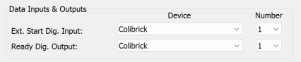
When the sequence is started, Clarity will be waiting for external start detected as a change in Digital Input state set as Ext. Start Dig. Input in System Configuration or by a start marker in digitally acquired detector signal data. The start of the measurement can be triggered by a digital input or by the signal from the detector.
Using sequence for automatic injections without an autosampler
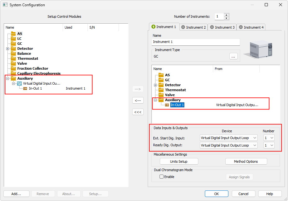
In such case, the sequence must be set to Active Mode. This is the default setting and you can activate it via Sequence - Options or by clicking the  icon. In this mode, the system sends a sequence start command to the sampler to execute the injection (via serial line or digital output configured as a Ready Dig. Output in System Configuration) and waits for a start signal from the sampler or the detector (received via communication line) or by change in the Ext. Start Dig. Input. When no autosampler is used, this process needs to be emulated by directly interconnecting the Ready Dig. Output with Ext. Start Dig. Input.
In case the A/D converter (Colibrick) is used, the leads for the IN1 and OutR1 on the Colibrick could be directly interconnected.
When no A/D converter is used, the Virtual Digital Input Output Loop auxiliary device (requires A24 LC or A23 GC Control license) cold be used to simulate the input/output needed - (those are virtually interconnected). The actual injection triggering depends on the connected hardware.
Note:
For more detailed info about adding new device (Virtual Digital Input Output Loop) see also Adding a new device.
For analyzers triggered by external contact, but not providing inject marker output signal, the start input could be connected in parallel to the Colibrick Ready Out cable (used typically for EA analyzers or Gow Mac process chromatographs).
In case the injection is performed by independently controlled valve the injection is then performed during the actual run by switching the valve (or valves) from the Clarity Event Table. When the injection valve is controlled through the GC, its switching must be programmed in the GC method Time or Event Table.
To set the Event Table:
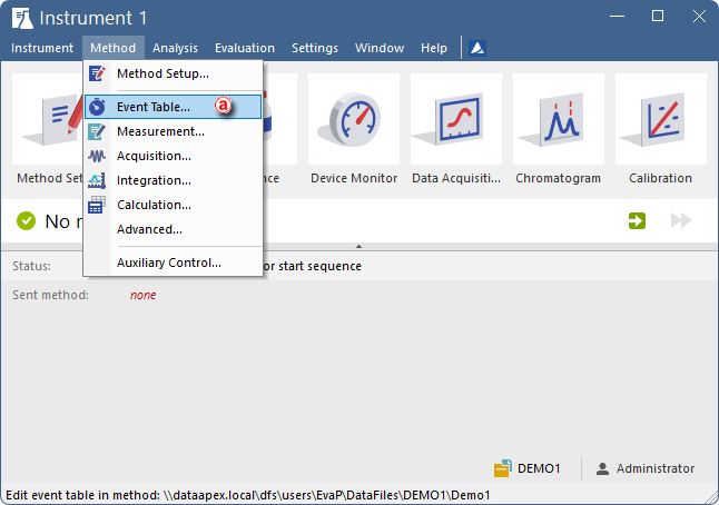
- Open the Method Setup on the Event Table ⓐ tab and prepare the method as necessary (or open an already existing method).
-
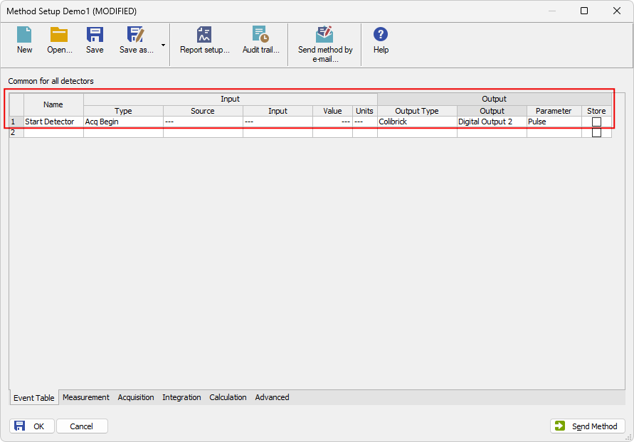
Fill in the first row of the table as shown in the figure below, and save the method. The example shown illustrates just one of several possible setups. It this example once the acquisition is started Colibrick sends a pulse via its Output 2, triggering a device connected there.
Note:
This example of the event table refers to the configuration where the valve is not part of the setup and is controlled via Colibrick. Alternatively, if the valve is instrument-controlled, the output would be connected directly to the valve instead of Colibrick.