AS + GC set - Active Sequence
In GC systems, the sample cycle is typically controlled by the GC, as the cool-down time of different systems varies due to the generally used temperature gradient. The sampler is thus synchronized with the GC by a signal wire (READY), allowing the next injection only after the GC gets to the READY state. The autosampler performs the injection and starts the GC using another signal wire (START). Any autosampler that is used in the Active Sequence
All commonly used autosamplers may be divided into two groups:
- Variant A: Autosamplers started by closing the contacts on the input (READY ).
- Variant B: Autosamplers started by opening the contacts on the input (READY).
Variant A - started by closing the contacts
The
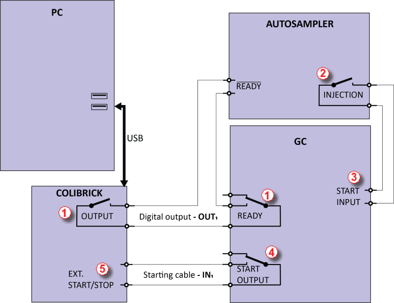
Wiring of the autosampler - variant A
The injection will start only after the both serially connected contacts (Clarity and GC) has been closed ①. After an injection, the autosampler will close the INJECTION contact ② and thus the command to start the temperature gradient program will be given ③. At the same time, the chromatograph will close the START contact ④, and thus the command to start acquisition will be given ⑤.
If the chromatograph does not have a START OUTPUT contact, then the starting cable
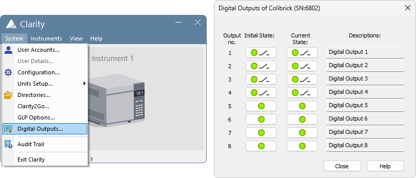
To have the contact on the Colibrick A/D converter opened in the initial state, it is necessary to set the Output Initial State item to HIGH in the Digital Outputs of Colibrick dialog as shown on Fig "The Digital Outputs dialog". This dialog is accessible from the Clarity main window through the System - Digital Outputs… command.
The start output, mapping of Clarity to individual digital outputs of the Colibrick A/D converter, can be set in the bottom-right corner of the System Configuration dialog, see Fig "System Configuration"
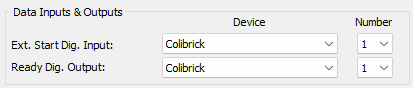
System Configuration - Data Inputs & Outputs for a GC set
Variant B - started by opening the contacts
In the second diagram, there is an autosampler wiring that conversely waits for output contacts to be opened. This requires different connection (marked by a circle).
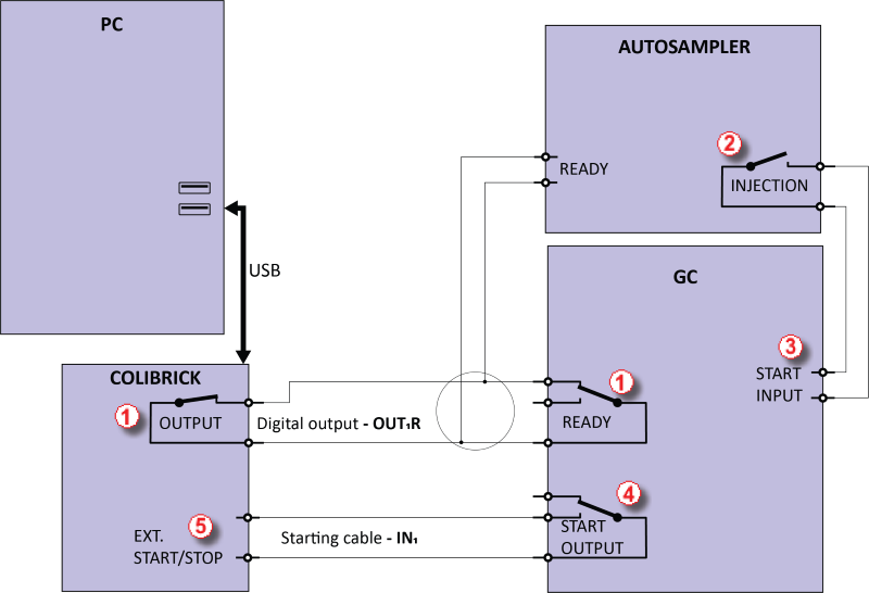
Wiring of the autosampler - variant B
The OUTPUT and READY contacts are connected in parallel, and the autosampler will start its operation after both contacts have been opened ①. After an injection, the autosampler will close the INJECTION contact ② and thus the command to start the temperature gradient program will be given ③. At the same time, the chromatograph will close the START contact ④ and thus the command to start acquisition will be given ⑤.
If the chromatograph does not have a START OUTPUT contact, then the starting cable INn must be connected directly to the INJECTION output of the autosampler.
To have the contact on the Colibrick A/D converter closed in the initial state, it is necessary to set the Output Initial State item to LoW.
External Start Digital Input and Ready Digital Output settings in the System Configuration dialog are the same as for Variant A.