Right section of System Configuration dialog
Sets the number of displayed Instruments and allocates equipment to the relevant Instruments.
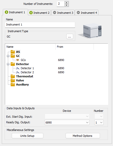
System Configuration - right section
Allocate the configured equipment (displayed on Setup Control Modules pane in the left section) to the relevant Instrument (in the right section) by “drag and drop” with the mouse or using the following buttons located in the center of the window:
| Button | Description |
|---|---|

|
Allocates selected equipment to an active Instrument. |

|
Removes selected equipment from an active Instrument. |

|
Removes all equipment from an active Instrument. |
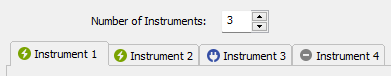
Provides the possibility to set the number of displayed Instruments. 1 to 4 Instruments can be displayed at a time, but you are only allowed to measure with as many Instruments as you have purchased (these are so called “online Instruments”). However, you can display more Instruments and use them for “offline” preparation of sequences and evaluation of chromatograms. Online Instruments have  icon in their tab header, while offline ones have
  icon. The tab(s) of any offline Instrument(s) will have the “Offline” inscription on them.
In the following image there are three Instruments set for display. The first two are online and the third is offline.
Tabs of individual Instruments
Tabs of individual Instruments. You can enter an Instrument name and Instrument type on each tab and connect drivers which will enable the measuring of a signal and directly control the chromatograph and other devices.
Tabs are indicated in the header with icons:
icon indicates an online Instrument, which is usable for the data acquisition (as well as to evaluate chromatograms, prepare methods, etc.).
icon indicates an offline Instrument, which cannot be used to acquire data, but can be used to prepare sequences or evaluate already measured chromatograms.
 icon indicates an Instrument that has been switched-off. The corresponding chromatograph symbol is not displayed in the main Clarity window.
Note:
The tab of a switched-off Instrument is accessible only to allow for the removal of modules previously installed on it.
Holds any arbitrary Instrument description and will be displayed in the main Clarity window above the picture of the chromatograph.
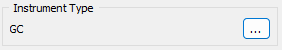
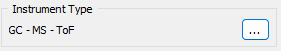
Use the  button to select type of analysis that will be performed on this Clarity Instrument. In addition to standard GC and LC types, optional Clarity Extensions provide additional Instrument Types (CE, GPC, EA, GC-GC and appropriate combinations with MS, MS-ToF, DHA, NGA and PDA).
Left mouse click on the button invokes the Instrument Type Setting dialog where the user can select a combination of instruments.
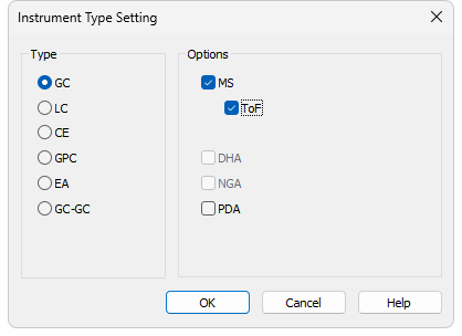
Instrument Type Setting dialog
For convenience the selected combination is displayed in the Instrument Type section.
Note:
Description of these Instrument types can be found in separate Clarity Extensions manuals.
Depending on the selected Instrument Type, the station’s main window displays an implicit symbol of a LC or GC chromatograph (if you have not set your own image) and the List of Equipment connected to the Instrument (see bellow) displays only the sections relevant to selected Instrument Type.
Holds any arbitrary Instrument description and will be displayed in the main Clarity window above the picture of the chromatograph.
Apart from default pictures of Instruments, it is possible to insert a custom picture. Click the picture of the chromatograph to open Instrument Image Setup dialog. To load a custom picture check the Custom Image checkbox and using the button you can browse for your own image.
Custom Image checkbox can be used to permit or forbid use of a user’s image.
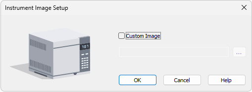
To select other then default image, Custom Image checkbox has to be checked. At that moment the button can be used to select an image file. There is only one image file for both the closed and opened Instrument image, the difference is provided by color overlay (closed image is darker). It is recommended to use preferably *.png or *.jpg image files.
If the custom image is not available, the preview will display a symbol of missing bitmap and in the main Clarity window the default image will be used.
List of the Equipment Connected to the Instrument
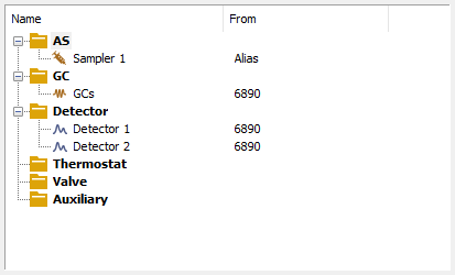
List of equipment connected to an Instrument
List of data sources for the Clarity station.
Sets direct control of the used chromatograph, detector or pump.
Sets direct control of the used autosampler.
Note:
Other categories may appear, including Valves, Fraction Collectors, Thermostats and other miscellaneous directly controlled equipment.
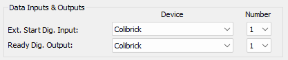
Setting of digital inputs/outputs for external Start/Stop:
Digital Outputs for external Start/Stop
The START synchronization between Clarity and the autosampler (eventually other devices such as Detectors, LC Pumps, etc.) is governed via cable pins for inputs and outputs (A/D Converter) or by serial port communication.The most common connections are described in Getting Started manual in the chapter "Connecting Autosamplers (AS)"
External Start Digital Input is assigned to the device and its specific pin that givesClarityinformation about injection being performed. Subsequently Clarity starts Data Acquisition.
Ready Digital Output defines the device and its specific pin through which Clarity informs other parts of the system that sequence can be run.
If you are measuring on multiple instruments using a single A/D converter, each independent instrument must have separate Ext. Start Dig. Input and Ready Dig. Outputpins configured.
If you have more than one A/D converter installed, in the Device combobox you can choose the one, whose digital inputs/ outputs you want to use. In the Number field of the Ext. Start Dig. Input line you can define which digital input the selected Instrument will use to start or stop the measuring. Similarly, it can be set which digital output the selected Instrument will use to permit sampling in an active sequence in the Number field of the Ready Dig. Output line. The option "--" (None) is enabled for selected devices. It can be used in the case when the START synchronization is ensured by other means (e.g. with directly controlled autosamplers over digital line).
In case no A/D converter is used and the devices are not offering digital inputs and outputs, it is suggested to use the DataApex Virtual Digital Input Output Loop (auxiliary device, requires A24 LC or A23 GC Control license) to simulate inputs/ outputs needed.
Units Setup button invokes the Units Setup dialog for respective instrument. Instrument 1 to 4 can each have set a different units and thus allowing a large variability.
See Units Setup for further instructions.
Method Options button invokes the Method Sending Options dialog.
This setting is individual for each Clarity Instrument.
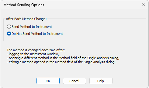
This dialog sets whether the LC/GC/AS method has to be sent to the instrument (device) at each change of the Single Analysis method.
Note:
Method Options button is not accessible for instruments with modules that send method automatically every time when is changed. Such modules are A/D converters Colibrick, INT7, INT9 or DEMO detector.
After Each Method Change in the Single Analysis dialog
Method changes by:
- Opening the Instrument window which automatically loads last used method from the given project.
- Changing the currently opened method in the Single Analysis dialog.
- Modifying method that is opened in the Method field of the Single Analysis dialog.
There are two possible regimes available:
Send Method to Instrument - Clarity will send the LC/GC/AS method to the instrument (device) automatically without prompt.
Do Not Send Method to Instrument - Clarity will not send LC/GC/AS method to instrument (device) each time a change occurs. Prior to running analysis, method must be sent manually.
Regardless of the setting, the LC/GC/AS method will be sent:
- From the running Active Sequence according to the Sequence Table.
- Manually using the Send Method button from the Single Analysis dialog and Device Monitor.
Caution:
Be aware that once a method is sent to the instrument, it can clear error that should stop the system (typically for LC system errors like overpressure or leak). When the method is sent to the Instrument without fixing of the error's cause it may cause the system run again. At the end the system could run and leak (for example) for very long time without anyone noticing the spilling. Therefore option Send Method to Instrument is not recommended for LC systems.