Connecting Autosamplers (AS)
This chapter describes the most common wiring of autosamplers. The configuration varies depending on the type of chromatograph (GC or LC)
Typical configurations are:
- AS + GC set - ACTIVE sequence
- AS + LC set - ACTIVE sequence
- AS + GC set - PASSIVE sequence
- AS with Clarity control module - ACTIVE sequence + A/D converter
- AS with Clarity control module - ACTIVE sequence + digital acquisition
All of the aforementioned configurations are described in more detail in the following chapters. If your device configuration does not correspond to any of these cases, contact us at support@dataapex.com.
In an ACTIVE sequence, the start is controlled by the station. Clarity sends the permission signal to the autosampler and waits until the sampler acknowledges the injection. Data acquisition will be started after the confirmation signal has been sent back to Clarity and the permission to another injection is disabled.
In a PASSIVE sequence, the start is controlled by the autosampler. Clarity waits for an external start signal from the autosampler and only after receiving the signal, it starts the sequence and data acquisition.
The START synchronization between Clarity and the autosampler is controlled via cable pins for inputs and outputs,
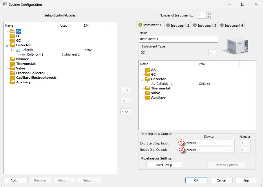
-
External Start Digital Input ① should be set to the device and its specific pin that gives Clarity the information about injection being performed. Subsequently, Clarity starts Data Acquisition.
-
Ready Digital Output ② defines the device and its specific pin through which Clarity informs other parts of the system that sequence can be run.