There are basically three means when Clarity decides to start the acquisition:
- User presses Run button in Single Analysis (user probably did manual injection and notifies Clarity that its time to start)
- Clarity is outside of run, but one of the controlled detectors starts to provide data marked as run data.
- Clarity gets the digital input marked as START from device over:
- Communication line (LAN, serial (RS-232), USB/GPIB)
- Wire as TTL signal (this connection requires an external A/D converter or other device offering digital input to Clarity)
The last case (3) is most typical way and this chapter describes how to assign digital input and output in Clarity for the most common wiring of devices (typically an autosampler). The setting is performed in System Configuration dialog through Ext. Start Dig. Input and Ready Dig. Output functions.
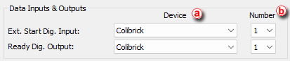
Data Inputs & Outputs
- Settings are specific for each particular instrument.
- ⓐ: Only devices configured on the Instrument are offered in device list.
- ⓑ: Input number list allows to select input number. Available inputs are specific for particular instrument and correct number depends on actual wiring.
External Start Digital Input
The device (in most cases the sampler) provides the injection state to Clarity over its digital output. This may be a real digital output on the device or just a simulated one (Clarity does not distinguish between the two). Selecting a right Ext. Start Dig. Input is necessary, because Clarity watches the state of the selected input all the time and reacts on its change.
Various devices are providing a lot of different inputs, and these may be used for other reasons, not only for analysis starting. The user needs to select the proper input which will allow the starting. For devices with virtual inputs, and in most cases also samplers with real outputs on the hardware, Start is signaled on output number 1.
After receiving START signal from a sampler, that notifies Clarity about performed injection, Clarity sends instruction to Start Acquisition to other modules (detector, column oven etc.) of the system .
Possible synchronization issues
Missing start of analysis
Situation could happen when there is configured compact HPLC (without sampler) and external sampler or controlled sampling valve. The sampler or valve lets Clarity know, broadcasts the analysis start and the HPLC needs to get the information from Clarity, otherwise it will never start running.
For some chromatographs, the settings of the module and its behavior are set in the module's configuration based on the actual wiring, and it is upon the person installing Clarity and setting up the configuration to set the whole system correctly.

For correct option always consider the source of the analysis start first (sampler, sampling valve, Start button on a instrument) and ask a question "What will happen if Clarity does not signal anything? Will the instrument run anyway?"
- If Yes - option should be set to This Device Starts the Run in Clarity
- If No - option should be set to Clarity Starts This Device
Ready Digital Output
Note:
Settings Ready Dig. Output in System Configuration dialog is relevant only for Active Sequence using sampler without AS Control module. Conversely is not relevant for controlled samplers used with AS Control module (signal over communication line), neither for Passive Sequence.
Ready Dig. Output defines the device and its specific pin through which Clarity informs other parts of the system that injection can be performed. After starting a sequence, controlled modules READY states are verified, Clarity triggers the Ready Dig. Output and changes its state, thus broadcasting to other modules of the system that sequence can be run. READY signal is received by the sampler that performs the injection and sends START signal. Then Clarity detects START signal and triggers again Ready Dig. Output and change its state, thus preventing the sampler to perform another injection.
Caution:
Using the Event Table in Method Setup other actions can be configured changing the parameters of Digital Output. Note, that if the same Digital Output is modified, it may cause conflicts in synchronization. Avoid using these inputs and outputs in the Event Table.
Settings Examples
Default assignment of the Ext. Start Dig. Input and Ready Dig. Output functions can be found in the manual for the corresponding hardware.
For most common wiring of autosampler see chapter Connecting Autosamplers (AS) or respective subsections in Getting Started manual.