LC Gradient
The Method Setup - LC Gradient dialog serves for setting up the LC instrument method.
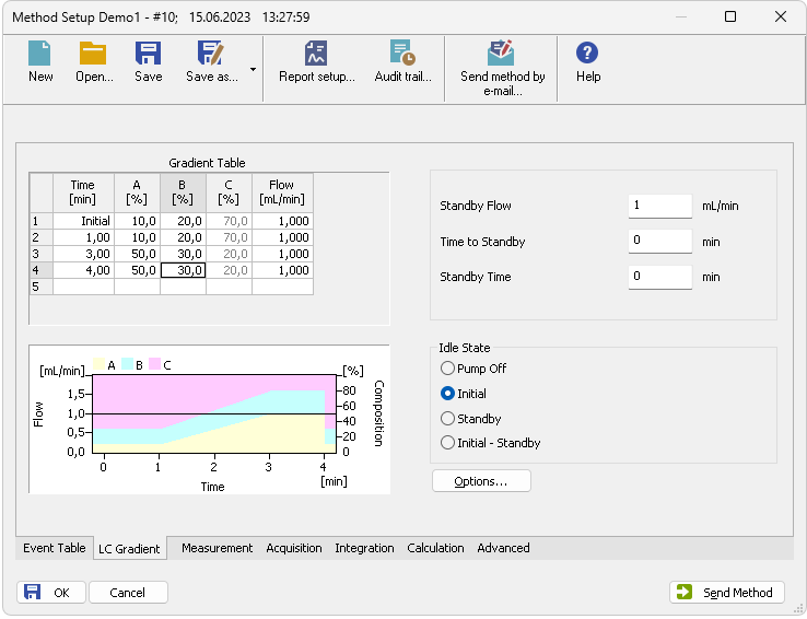
Method Setup - LC Gradient
A table for setting the composition of the mobile phase and the overall flow rate as a function of time. To prepare the cell to receive values, click it by the left mouse button; the cell will highlight by dots. A cell that fails to highlight is not available for editing.
Sets the time at which the ratio of flow rates and the overall flow rate correspond to the values entered in the corresponding row. (These values vary continuously from one time to the next in a manner ensuring that the conditions specified in the next row are satisfied).
Represents the percentage of a component. The designation XXX1-4 is in fact replaced by the name of the component (items Solvent 1 - 4 in the Gradient Options dialog). Should you enter a component value such that the sum of all values exceeds 100 %, the percentage in the last column is automatically adjusted; if the percentage of the last compound is already zero, the value of the currently entered component is adjusted instead. The flow rate of a compound is calculated by multiplying the overall flow rate (indicated in the Flow column) by the corresponding percentage divided by 100.
Indicates the overall flow rate through the column. The entered value applies to the time specified in the corresponding row.
The graph depicts the percentage of components as a function of time together with the overall flow rate. Data are taken over from the Gradient Table. Changes effected in this table are immediately reflected in the graph. Legend in the header of the graph indicates the assignment of colors to individual components. The assignment is fixed and individual components are displayed in the graph from bottom to top. The flow rate is displayed as a black line.
The graph has two vertical axes: the axis on the left refers to the mixing ratio, the one on the right to the overall flow rate.
Sets the overall flow rate through the column in the STANDBY state reached after the last row of the table has been performed and the time period defined in the Time to Standby field has passed. The duration of this state is defined by the Standby Time item. The ratio of individual components in the respective STANDBY and IDLE states is given by the first row of the Gradient Table (the Initial row).
Indicates the time during which the flow rate and mobile phase composition changes continuously between the last values entered in the table and the values defined by Standby Flow field and the Initial row mobile phase composition.
This time is included in the analysis time (the Instrument is in the CONTROL state). In case when the Time to Standby is zero, there is step change from flow and components percentage specified on the last row of gradient table to that specified for STANDBY state.
The time during which the flow rate is maintained at Standby Flow. This time is included in the analysis time (the Instrument is in the CONTROL state).
An item specifying the overall flow rate through the column outside the instrument method. The following options are possible:
The flow rates of all components are zero.
Caution:
Be careful as this setting may damage the column in some cases.
The flow rate is defined by the first row of the gradient table (the Initial row).
The flow rate is the same as in the STANDBY mode and, accordingly, corresponds to the value entered in Standby Flow field.
When the Method is sent to pump or the analysis has started, the flowrate is defined by the first row of the Gradient Table (the Initial row). After the last row of the table has been performed and the Time to Standby has passed, the overall flowrate is set to value entered in the Stand By Flow.
The IDLE state comes into effect each time an Instrument is opened, at the end or after abortion of an analysis by the Abort command, and is also maintained after the Clarity program is shut down.
The mixing ratio of individual components in both the IDLE and STANDBY states is given by the first row of the Gradient Table (the Initial row).
Note:
There is a step change in the flow and components percentage from the values specified for the STANDBY state to those specified for the IDLE state if the Idle State field is not set to Standby.
Opens the Gradient Options dialog that allows the setting of minimum and maximum pressure limits and solvent names.