|
|
Serial Number (S/N) and User Code (U/C) are two essential identifiers for our software. The S/N is a 7- or 8-digit number representing the station's serial number. It is saved in the HW key and is permanent, meaning it doesn't change with the Clarity configuration change. Whenever you ask for technical support at support@dataapex.com, you will have to provide your S/N. On the other hand, U/C is a 16- or 17-digit code that defines the configuration and version of the chromatography software. It is formed from letters and numbers and unlocks the specific Clarity configuration in a specific HW key. You will need to enter the U/C during the installation process, and when the configuration changes, you must set the new U/C (usually received via email) in the Clarity main window - Help - User Code... dialog. S/N and U/C can be found on the packing list, and installation media. You can also read the S/N and U/C from within the software (main window – menu Help/About). 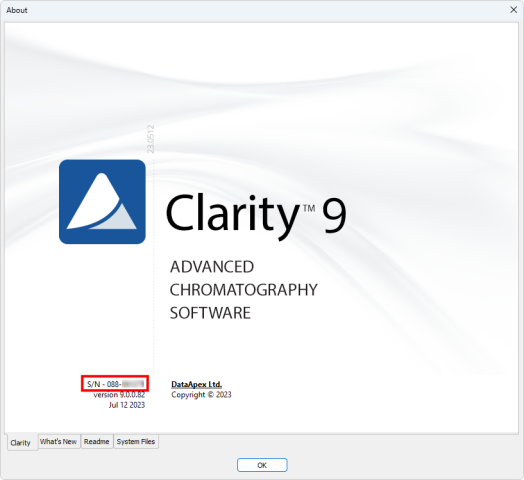 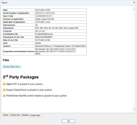
|
29.04.2026 |
|
|
When Clarity (Lite) is started, an error message stating "Missing HW key" may appear. This issue arises when the required hardware key is not detected by the system. If you encounter any problems, the first step is to check the USB port the key is plugged into. Try moving the HW key into a different USB port on the PC or another PC. Most issues are related to the USB port's energy-saving settings in Windows or a faulty USB port.
 The Rockey USB ND does not require any separate driver installation; once plugged into a USB port, all necessary drivers are automatically installed. For problems encountered in the case of older keys, see the section below. Make sure that the LED diode in the key is steadily lit. If it is blinking or it is not lit at all, the hardware key may be faulty, and you will need to send it to us for inspection. Please contact us at support@dataapex.com in such case. Old hardware key typesThe older hardware key types require drivers to be installed prior to their use. The Rockey USB might not be functional due to installation of a wrong driver. This occurs if the key was connected to the PC before Clarity was installed. This can be solved by manually uninstalling the wrong driver, restarting the PC, and installing the correct one. To do so, the driver installer is located in the Clarity\BIN\HW_DRIVERS\ subfolder.  
|
29.04.2026 |
|
|
Moving Clarity to a new PC is possible, but before you proceed, check the following key areas: - Clarity version
Older versions may not run on modern Windows systems. You might need to purchase an upgrade if you're coming from an old version (e.g. Clarity 5.x on Windows XP or Vista). For full details, see Clarity computer requirements and compatibility and our Upgrade Policy. - Hardware key
Older RkUSB keys (typically blue) will not function correctly on Windows 10 or Windows 11 systems, as their driver is not compatible with the "Memory integrity" option in Core Isolation security settings.
We recommend replacing the old RkUSB key with a RkNDUSB (grey). To do so, use part number S016.
To identify your hardware key:
In Clarity (Lite), go to Help - About - System files. Under Acquisition and hardware devices, you will see:- Key Rockey 4ND for the current type (RkNDUSB) – grey/transparent casing (a)
- Key Rockey USB for older type (RkUSB) – blue casing (b)

- A/D converter
Some older A/D converters may not work on modern PCs, and we recommend replacing them with a Colibrick, our current A/D converter designed for compatibility with modern systems:- U-PAD is only supported on 32-bit operating systems and cannot be used on Windows 11.
- INT7/INT9 require a PCI slot, which most modern computers no longer have.
- Data and settings
If the old hard drive is still accessible, you can transfer your data and configurations. Detailed steps are available in this FAQ article.
|
15.04.2026 |
|
|
Clarity (Lite) Demo is a demonstration version of the Clarity (Lite) software. Clarity (Lite) Demo has the same functionality as the Clarity (Lite) version, except that data acquisition is simulated and the import function is disabled. Only demo data is allowed in the Clarity (Lite) Demo version. Clarity (Lite) Demo is freely available and is not protected by a HW key or user code.
|
09.04.2026 |
|
|
Only one Clarity station can run on a single PC at a time. Within that station, up to 4 independent chromatograph configurations can be set up — one on each available Instrument with an independent time-base. Up to 32 signals/channels can be acquired on one Instrument. The core software (p/n C50) includes only one Instrument. If needed, up to 3 additional Instruments can be added by purchasing Add-on Instrument (p/n C55). Please note that additional limitations may also be given by the controlled instrument itself. For example, due to communication protocol constraints, only one Shimadzu LC-10/20 system may be controlled by one Clarity station.
|
27.03.2026 |
|
|
User privileges settingsClarity users must have read/write access to the Clarity system and data files. The default C:\Clarty (C:\ClarityLite) directory inherits the Read Only status from C:\ on administered systems. It is recommended to install Clarity for the User that will use Clarity under the "As Administrator" option. If not possible, contact your local administrator to change the settings. Antivirus programsAntivirus programs usually do not interfere with Clarity functionality. But two areas may pose problems for the correct functioning of Clarity: - Antivirus is causing processor overload in certain situations, which may leave insufficient memory resources for Clarity.
- Antivirus continuously monitors files frequently updated by Clarity (.raw, .audit, etc.), which may be unjustifiably marked as a threat to the PC.
Windows UpdatesAutomatic Windows updates are in the default settings that force the unattended computer to restart regardless of running programs - only a warning message will appear. Please note that the first two options (Automatic updates or Download updates) may result in a forced computer restart. We recommend installing and operating Clarity on a PC with updated OS, only the forced restarts pose a potential problem to Clarity. In Windows 10 and 11, it is not possible to forbid the updates; just pause updates for a short period of time and install them manually to avoid forced restarts. Go to Settings - Windows Update - Advanced Options - Pause Updates In Windows 7, 8.1 go to Control Panel - System and Security - Windows Update- Change settings.
Choose one of the options for automatic updates: - Never check for updates.
- Check for updates, but let me choose whether to download or install them.
Ask your local administrator to choose one of the options described above on administered systems. See also Table of compatible Windows OS, Clarity SW and DataApex Hardware.
|
24.03.2026 |
|
|
Our recommended solution is MultiCOM, especially if you need to connect several devices.
MultiCOM is a 6× RS232-to-USB converter designed for use with Clarity and is the best choice when your computer does not have enough serial ports. 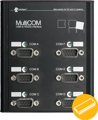 Third-party USB-RS232 adapters may also work, but compatibility can vary depending on the chipset and driver quality. Some adapters based on Prolific chipsets have caused communication problems in practice. Third-party USB-RS232 adapters may also work, but compatibility can vary depending on the chipset and driver quality. Some adapters based on Prolific chipsets have caused communication problems in practice.
|
24.03.2026 |
|
|
Yes — you can move Clarity or Clarity Lite to a new PC.
The license is tied to the HW key, so the software can be installed on another computer, but it will only run with the correct HW key connected. Recommended procedure: - Get the installation package - the latest version can be downloaded from our website, www.dataapex.com, section Downloads; you need to be registered and logged in.
- Plug in the HW key.
- Install the software on a new computer.
- Ensure all necessary drivers and control modules are installed – some may not be included in the Typical installation.
- Enter the user code matching the HW key.
- Connect the hardware (MultiCOM, A/D Converter, etc.).
- Copy your settings and data into the appropriate files.
- Copy the system files (Clarity.cfg, *.dsk, Clarity.psw) from the old computer to the Clarity\cfg folder on the new PC.
- Copy the data files (including the Projects and Common) from the old computer to the Clarity\Datafiles folder on the new PC.
You can also use the Archive/Restore function (not available in Clarity Lite) to transfer the required data files to the new PC. When moving Clarity from an older PC or an outdated Windows system to a new computer, compatibility issues may occur in some cases. For more information, see the related FAQ.
|
24.03.2026 |
|
|
In many cases, yes — but only for data acquisition. Direct instrument control from Clarity is not available. - If the device is listed in D004 with a Colibrick interface, it indicates that analog data acquisition using the Colibrick A/D converter is supported, while the instrument itself is operated locally.
- If the device is not listed in D004 at all, it may still be usable with Clarity for data acquisition, but the presence of a standard analog output must be verified in the device documentation.
When using Clarity (Lite) with the Colibrick A/D converter, Clarity acquires and processes the analog signal, while all instrument settings and control are performed directly on the device (for example via its own keyboard or control panel). Basic autosampler synchronization is also supported as part of this setup.
|
17.12.2025 |
|
|
Clarity Extension is an optional software extension that brings additional capabilities to Clarity. The information about available extensions, including technical documentation, can be found on our website. We currently offer extensions for Photo Diode Array (PDA), Mass Spectrometry (MS), Gel Permeation Chromatography (GPC), Natural Gas Analysis (NGA), Detailed Hydrocarbon Analysis (DHA), Capillary Electrophoresis (CE), Elemental Analysis (EA), and System Suitability Test (SST).
|
08.08.2025 |
|
|
No. Clarity is a standalone workstation software. It is not a client-server system — each Clarity station operates independently and must be connected locally to the instrument. However, Clarity supports limited network functionality: - Data (chromatograms, methods, calibrations, etc.) can be stored on a shared network drive, such as a server.
- These shared data can then be accessed from other Clarity stations — including Clarity Offline, which allows method preparation and data evaluation from a different PC (e.g., elsewhere in the lab or from home).
- Multiple Clarity and Clarity Offline stations can coexist in the same network setup.
Limitations: - No centralized user or data management.
- No remote acquisition or instrument control from other stations.
- No real-time signal monitoring from other PCs.
For more information and setup instructions, see the Clarity in Network manual (document M215).
|
15.07.2025 |
|
|
No. Clarity Chromatography Software is a file-based system, not a database-based application. All chromatograms, methods, sequences, calibrations, and other documents are stored as individual files within a structured directory tree. This provides transparency, flexibility, and easy access to all data without requiring a database engine. Despite not using a database, Clarity can still be used in regulated environments. When properly configured, it meets the requirements of 21 CFR Part 11 and other data integrity guidelines. More information is available in the guide Clarity in Regulated Environment (PDF) and on the dedicated page on the DataApex website.
|
10.07.2025 |
|
|
Clarity Chromatography Software supports two main ways to connect instruments: - Digitally Controlled Instruments – Clarity communicates with the instrument directly, can control it, and collects data digitally.
- Analog Instruments – The instrument sends an analog voltage signal, which is digitized by a A/D converter Colibrick, but Clarity cannot control the instrument except for some basic synchronization – all settings must be configured manually on the device itself.
Each option offers a different level of integration, automation, and data quality. 1. Digitally Controlled Instruments – Full Control and CommunicationThese instruments are fully integrated with Clarity using a digital interface (RS232, USB, LAN, etc.). Communication is bi-directional: Clarity can send commands to the instrument and receive data, status, and error messages. Key benefits: - Control instrument parameters directly from Clarity (e.g., flow, temperature, gradient, wavelength).
- Start/stop the device or switch valves remotely.
- Receive feedback from the instrument (diagnostics, status, alerts).
- Synchronize the whole workflow, including autosamplers and detectors.
- Automate complex sequences (startup, conditioning, analysis, shutdown).
- Audit trail: All settings used during the analysis are logged automatically.
This setup is ideal for labs that need high efficiency, traceability, and regulatory compliance. 2. Analog Instruments – Signal Only, No ControlAnalog instruments do not communicate with Clarity. Instead, they generate an analog voltage signal (typically 0–1 V or 0–10 V), which is digitized by a A/D converter Colibrick before being processed and displayed in Clarity. These instruments provide data only — no direct parameter control or feedback is possible, though basic synchronization (e.g. start signals, digital outputs) is supported. What you can do: - Acquire the detector signal through an A/D converter.
- Trigger external devices (e.g., autosamplers) via digital outputs.
- Start acquisition using an external start signal.
- In some cases, control gradients via analog output using Zebrick D/A converter.
What you cannot do: - Set or change any instrument parameters from Clarity.
- Monitor instrument status or errors.
- Synchronize methods or workflows.
- Automatically log instrument settings.
All adjustments (flow, temp, wavelength, etc.) must be done manually on the instrument's physical interface.
|
30.06.2025 |
|
|
Windows 10 and 11 rolled out updates that change some behavior in the registry, which in some cases (mainly when Clarity installation has been run recently) causes installation not to start. Problem is fixed in Clarity 10.1. The problem should be resolved by restarting the PC, alternatively you can manually fix the registry and proceed with the installation. To remedy the problem manually, please clean the registry by following the steps below. To do that, you may need administrator privileges in the Windows OS. (Image below provides details to accompany the steps.) - Start Registry Editor (either via Windows search or using Windows key + R and executing "regedit")
- Navigate to: Computer\HKEY_LOCAL_MACHINE\SYSTEM\CurrentControlSet\Control\Session Manager (path can be copied to Navigation bar)
- Select and open PendingFileRenameOperations
- Delete all its contents
- Confirm the dialog
- Run the installation
 
|
05.06.2025 |
|
|
Clarity installation requires a specific version of Microsoft .NET Framework, which may not be installed or enabled on the computer by default. You will be notified by the Clarity installer which version of .NET is missing on your PC. Some external control modules and their components may also require a different version, which is not controlled by the Clarity installer. There are three ways to obtain the required versions of .NET framework: - Install the version of .NET supplied in the installation media folder dotNet.
- Download the version of .NET from the internet, using the links below, and install it.
- Turn on Windows updates to download the latest version.
Required versions of .NET Framework- Clarity installation requires a version of .NET Framework 4.8 or higher
- Testa Flowmeter control module and Installation Qualification for Knauer HPLC requires .NET Framework 3.5 SP1
.NET Framework installationOn Windows 7, download the respective versions using the link below: Click here to download .NET 3.5 SP1 Click here to download .NET 4.8 (this includes all previous 4.X versions) On Windows 8.1, 10 and 11 follow these steps: - Go to Start Menu –> Control Panel –> Programs and Features –> Turn Windows features on or off. (Or in the Run dialog, enter "optionalfeatures".)
- In the displayed Windows Features dialog, check the .NET Framework 3.5 (includes .NET 2.0 and 3.0) and .NET Framework 4.X.
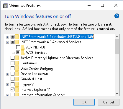
- Click OK, and the selected option will be installed and enabled.
Note:
Installing the .NET framework may require additional Windows updates. Always follow the instructions supplied with each version of .NET you are installing. It contains information about additional updates and security fixes.
Installation of .NET 3.5 is not always smooth in Windows 10, consult with your IT to find the best way to install it.
|
30.05.2025 |
|
|
The control of Shimadzu Nexis GC-2030 GC, Brevis GC-2050 GC and Nexera LC-40 HPLC is available in Clarity - Shimadzu Edition (p/n C50-28).
It requires a Shimadzu license for each connected instrument p/n A23-001 for GC-2030 or GC-2050 and A24-001 for Nexera HPLC Series.
Clarity - Shimadzu Edition is available only in Europe. Examples: Configuration for Clarity Shimadzu Edition with one Nexis GC:
p/n C50-28 Clarity Shimadzu Edition for 1 Instrument
p/n A23 GC control
p/n A23-001 GC Shimadzu license for one GC
optional:
p/n A26 AS control (in case there is a Clarity controlled autosampler) Configuration for Clarity with two Nexera HPLCs:
p/n C50-28 Clarity Shimadzu Edition for 1 Instrument
p/n C55 Add on Instrument
p/n A24 LC control
p/n A24-001 LC Shimadzu license for one HPLC, 2x
optional:
p/n A26 AS control (in case there is a Clarity controlled autosampler)
p/n A29 PDA extension (in case Nexera includes a PDA detector) Configuration for Clarity with one Nexis GC and one Nexera HPLC:
p/n C50-28 Clarity Shimadzu Edition for 1 Instrument
p/n C55 Add on Instrument
p/n A23 GC control
p/n A23-001 GC Shimadzu license for one GC
p/n A24 LC control
p/n A24-001 LC Shimadzu license for one HPLC
optional:
p/n A26 AS control (in case there is a Clarity controlled autosampler)
p/n A29 PDA extension (in case Nexera includes a PDA detector) When ordering an upgrade from Clarity to Clarity Shimadzu Edition (p/n C620-28), do not forget to add a Shimadzu control license p/n A23-001 or A24-001.
|
30.05.2025 |
|
|
Clarity is a 32-bit process, which means it can use the max of 2GB RAM, but if you use more than one demanding instrument, it can still be beneficial to have 8 GB RAM, so the PC has enough RAM left for OS and other apps. If you get the "Out Of Memory" error, e.g., when opening measured chromatograms while running a sequence, it may be caused by using a particular method, which has been saved over and over again due to some modifications. Every saving of such a method results in creating another method version (the number of versions is displayed at the top of the Method Setup dialog behind the method name as "- #number"). These versions increase the Method file size; memory can be depleted when such a large method is used, forcing the software to misbehave. As a remedy: - Try to save the method using the command Save As under a new name. This will save your method without previous versions, decreasing the file size.
- Do not use "Open chromatograms in Overlay" when running a Sequence.
- Do not open resulting chromatograms when Sequence is running (Disable the checkbox in the Open column).
- Limit the number of chromatograms included in printing of a summary report.
|
29.05.2025 |
|
|
In such case, it is recommended to check Colibrick Setup in the System Configuration window. Synchronize Start with Digital Input should only be enabled when one of Colibrick's digital inputs is configured as Exr. Start Dig. Input:. Furthermore, Synchronize Start with Digital Input and Exr. Start Dig. Input: must be set to the same Digital Input.
This change was made because the wrong setting led to random issues with analysis starts in previous versions. 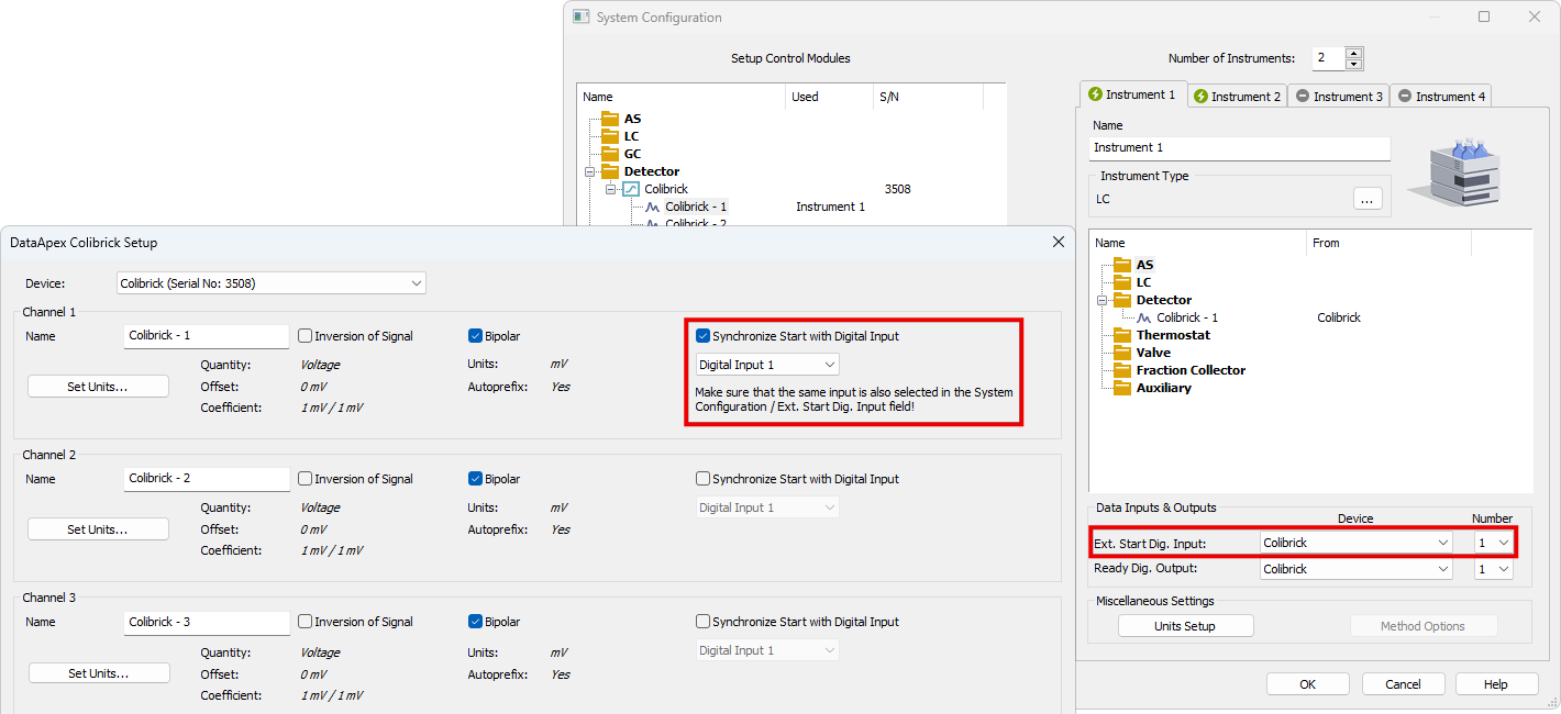
Synchronize Start with Digital Input enables a faster and more accurate synchronization of channels with the start signal. The start of the analysis is defined by a marker in data points rather than by detecting the change in Digital Input. The difference is in the order of hundreds of milliseconds, which means that it is important only for very short analysis. When measuring multi-detector chromatograms it will minimize the time shift between detector signals and thus improve the detection of peaks.
|
12.12.2024 |
|
|
Bar code scanner support is implemented within a few autosampler control modules (Spark Integrity, HTA HT4000, …). The read bar code will be available as the %f variable for use in SampleID, Sample, or Filename fields. Hand-held scanners (emulating keyboard) could be used to fill in the values in the sequence table – the terminating character should be set to Enter, and the setting in the User Options dialog - General tab - Sequence Table - On Enter section should be set to Move Down option to move the focus to the next row after the Bar code value is read. For versions before 9.0, the option to set the terminating character to Down Arrow in the scanner will be advantageous; otherwise, moving to the next row using the mouse/keyboard is necessary. 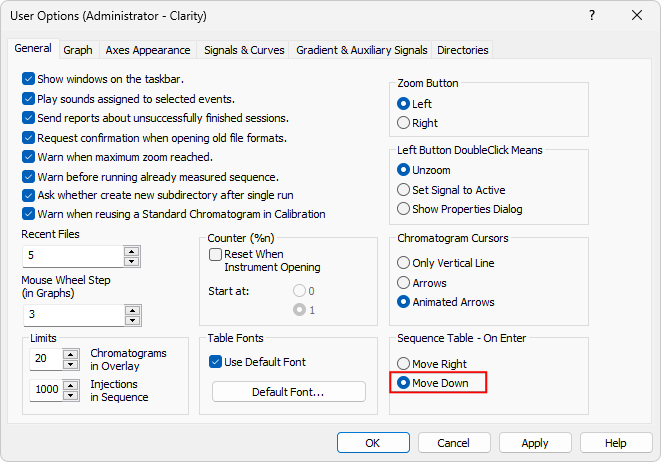
|
12.12.2024 |
|
|
We highly recommend registering every license. Only registered users can access our download center and are entitled to obtain a free upgrade to the new version if they are in the one-year free upgrade period. Registration is also a prerequisite to contacting customer support.
|
10.12.2024 |
|
|
Clarity Lite is a simplified version of Clarity Chromatography Software. It supports only one Instrument (one time-base) with one A/D converter for analog acquisition. Clarity Lite cannot be extended by optional extensions and control modules. It also does not have the GLP features. Other SW differences are described on the Clarity software comparison table page.
Clarity Lite can be upgraded to Clarity (p/n C540).
|
10.12.2024 |
|
|
It is not possible to install Clarity on Windows 10 LTSC releases, where .NET Framework version 4.8 or newer cannot be installed (this should apply to Windows 10 Enterprise LTSC 2015). Clarity installation requires .NET Framework version 4.8, introduced as part of Windows updates in 2019 (Windows build 1903). Importantly, DataApex cannot guarantee complete Clarity functionality in LTSC Windows releases, as they are not among supported OS (only OS with the latest updates is fully supported) and are not properly tested with Clarity. All Software and Hardware requirements are listed here. You can test whether it is possible to install Clarity to the system by downloading and installing Clarity Demo.
|
03.12.2024 |
|
|
You can read your software version from the software main window in the Help – About menu. 
|
03.07.2024 |
|
|
If you purchase a software upgrade for your Clarity or Clarity Lite Software license, you will get a free upgrade for your associated free Clarity Offline. You only need to list the Clarity Offline S/N on your purchase order as well. An educational discount also applies to software upgrades.
|
03.06.2024 |
|
|
Most problems with Colibrick are related to the USB power supply. So if USB hub is used, we recommend using a hub with an external power source. It's important to note that Colibrick is sensitive to communication delays. These delays can be caused by issues with the computer's hardware or software, such as processor overload, low RAM memory or running processes blocking the processor or communication lines. If there is no communication for more than 10 seconds, an error message will be displayed, such as "No data from Acquisition" or "No data received for...". This will cause the acquisition to stop and the running sequence to be interrupted. If the problem is temporary, resending the method may solve the problem. Otherwise, try disconnecting and reconnecting the USB hub. To check for issues, use the Task Manager to inspect the processor load and processes consuming a large amount of CPU time or memory. Programs that can cause issues include incorrectly set anti-virus programs that continuously check file types used by Clarity during data acquisition. To avoid this, disable the *.raw, *.prm, *.audit, and *.tmp file types for scans. Other programs that monitor files on exchangeable media, such as programs for organizing and presenting pictures, music or video may also interrupt the acquisition. It's also important to note that any actions started during the acquisition, such as printing to a slow USB or network printer, large file transfers over network or USB, connecting or disconnecting USB devices, computer entering sleep mode can cause the acquisition to be interrupted. Finally, it's worth noting that the communication problem with Colibrick can be avoided by connecting the USB hub to the USB C connector on the PC.
|
13.05.2024 |
|
|
The "No Data received for 10 sec" or "No data from Acquisition..." messages mean what they say, no data were received from a detector or A/D converter (Colibrick, etc.) for a certain time. It may be caused by several cases: - In most cases, there is some problem on the computer - processor overload, interference on the USB bus, time-consuming net search, or backup operations blocking the communication for some time. The error invoked will stop an acquisition or interrupt the sequence.
Suspected programs are incorrectly set antivirus (continuous checking of file types used by Clarity during data acquisition - raw, prm, audit, tmp should be avoided), programs monitoring files on exchangeable media (i.e. programs for organizing and presenting pictures, music, or video, including some CD/DVD burning programs). One such persisting problem was reportedly solved by removing the Roxio Burning software.
This will occur more frequently on slow computers, the triggering action may be processor overload or some programs blocking the communication for an extended period.
- In some cases, Windows may suspend the power of the USB HUB in the computer and this unexceptionally causes a loss of connection to connected HW (e.g., Colibrick). Try to check the Device Manager dialog - Universal Serial Bus controllers. Display the Generic USB HUB Properties dialog - Power Management tab. Set Disabled for option Allow the computer to turn off this device to safe power. In case the problem is temporary, sending the method again may solve the problem. If not, disconnect and reconnect the USB HUB.
The above-mentioned problem with communication was not observed when the USB hub is connected to the USB C connector on the PC.
|
13.05.2024 |
|
|
Clarity stores the IP address of the device detected during autodetection in the configuration and if it changes, it is unable to communicate with the device. Some devices use IP adress assigned by DHCP server in default settings.
If the system is connected directly to the computer or via a switch, it is necessary to set static IP addresses in the devices and in the LAN card in the computer (preferred solution). Refer to the device manual or contact device manufacturer/supplier for how to change the device setting to a static IP address.
If the system is connected directly to the computer via router, it is possible to use DHCP IP address assignment, but you must ensure that the assigned IP addresses do not change. The same applies for connections via an internal network, where the cooperation of the network administrator is required to set the IP address.
|
13.05.2024 |
|
|
Yes, it can. However, the philosophy of use is slightly different. The peak areas of a selected group of peaks are summed, and the group can be named and calibrated as a single compound. Please refer to the corresponding parts of the Reference and User Guides. Especially in the calculation of the Result table Total line and Amount % column, there are potential problems, if the calculation procedure is not understood correctly.
|
10.05.2024 |
|
|
If you experience a long delay when downloading the Clarity installer from www.dataapex.com and the download process seems to hang when it's almost complete, it's possible that your anti-virus software is scanning your web communication and downloads for viruses, which can cause the delay. The delay duration depends on the file size and anti-virus SW used.
|
10.05.2024 |
|
|
If your PC and chromatograph are connected directly via LAN and autodetect is not possible, continue with the following procedure: - You need a cross-over ethernet cable (a straight-through cable is not recommended).
- Open Windows Settings - Network & Internet - Ethernet tab - Change adapter options - right mouse click on the Local Area Connection and choose Properties.
- In the Local Area Connection Properties, choose Internet Protocol Version 4 and click the Properties button.
- Check the radio button in the Internet Protocol Version 4 (TCP/IPv4) Properties window. Use the following IP address.
- Fill in the IP address.
- The first three positions define the network and must be the same as in the device's IP address.
- The last position defines the device and must be unique within the network, so do not use one of the connected instruments. Eventually, other Ethernet boards within the computer must not share the same network.
- The subnet mask needs to be 255.255.255.0

|
10.05.2024 |
|
|
Yes, it is. Simply take your HW key and plug it into another PC. You can install Clarity (Lite, Offline) on as many PCs as you like using the same user code. Clarity will work properly on the one PC with the HW key connected.
|
10.05.2024 |
|
|
Yes, Clarity can be connected to any LIMS by importing/exporting text files. Results can be exported in various formats to the LIMS, and the sample info can be imported from a TXT file into Clarity Sequence, which you intend to process. Please see our manual describing the Clarity cooperation with LIMS: Cooperation with LIMS systems.
|
10.05.2024 |
|
|
Most probably, you need an appropriate User Code (u/c) only. HW key keeps the basic information about serial number XX-YYYYY (event. XX-YYYYYY) only. All information about valid versions, a number of instruments, extensions, and control modules are part of the User Code.
|
09.05.2024 |
|
|
An upgrade to the new major Clarity version (change in the first number before the dot) is paid and requires a new user code. Please refer to your price list under p/n C500 (C400/C591). All minor version updates (change in any number after the first dot) are provided free of charge and do not require a new user code. For more details, please refer to Clarity Upgrade Policy. The installer of the current release version can be downloaded directly from the station, or from our websites.
|
09.05.2024 |
|
|
The Clarity software has several system files that are important for storing various data related to its functioning. The list of the files with default paths: - C:\Clarity\Cfg\Clarity.cfg
This file stores hardware configuration information, along with information about the last user who logged in to a specific instrument, and custom instrument pictures used in the Main window. - C:\Clarity\Cfg\*.dsk
This file stores information about the last used project (*.prj) and individual user preferences such as windows configuration and layout, tables and graph preferences, user columns, and more. - C:\Clarity\DataFiles\Projects\*.prj
This file stores information about project subdirectories (the project directory has the same name as the project *.prj file) and the last used method, sequence, SST method, chromatograms and other files. - C:\Clarity\Cfg\Clarity.psw
This file stores the list of users and their access rights. - C:\Clarity\Cfg\Clarity.sno
This file stores the identification of the station.
It is recommended to back up these files to prevent data loss in case of an accident. Please note that up to version 6.2, the Cfg subfolder did not exist, and the files were present in the root folder.
|
09.05.2024 |
|
|
Most chromatography systems use a proprietary data format (the main reason is the belief that it ensures data integrity for GLP-related requirements). To open and process such chromatograms in Clarity, they must be first exported from the original software into a suitable format. The most commonly used formats are AIA (.cdf files) or ASCII (.csv, *.txt, *.asc, and others). Clarity can import such files (only the chromatogram data, not the integration method or result tables) and process them using the current instrument method. Chemstation - The export is available with full menus active in the Data Analysis view (menu File, command Export file, AIA file....). Due to the way the Chemstation exports the files (they are always named signal01.cdf and stored in user-named folders; batch export is not supported), the processing is not very convenient and will be quite laborious for a large number of files.
- The export of DAD data is even more complicated, if not impossible (you will have to export each wavelength separately and combine them to the format that can be imported to Clarity).
EZ Chrom - The chromatograms can be exported during processing, in the Advanced Method Options, Export tab for option Chromatogram the AIA and ASCII formats can be selected.
- The ASCII *.asc file format is supported by Clarity both for chromatograms and 3D data. AIA files can be used as well.
|
09.05.2024 |
|
|
Two most recent major versions of Clarity and Clarity Lite.
|
30.04.2024 |
|
|
We release upgrades (major versions) every 1–2 years. There are also 2–3 updates (minor versions) between upgrades.
|
30.04.2024 |
|
|
Yes, if you have registered your Clarity (Lite) at the DataApex website, we will automatically send you the new user code when a major version is released. You will receive an email with a new user code to the email address used in your registration.
|
30.04.2024 |
|
|
This situation is unpleasant because the loss of the HW key equals the loss of the license. The software and a new HW key must be repurchased. We include warning labels attached to HW keys in each delivery.
|
30.04.2024 |
|
|
A user needs to fill out the "Registration of a university package" form that is available on our website. A description of the registration procedure is a part of Clarity Offline delivery.
|
30.04.2024 |
|
|
If you have bought an extension or control module license, you will get a new user code for the latest SW version and have to use the version compatible with the user code (if you have it, there is no need for reinstalling). On top of that in the case of a new control module, reinstallation depends on how you installed Clarity originally (typical, full, or custom installation). If you miss any control module in the System Configuration window, you must reinstall Clarity.
|
30.04.2024 |
|
|
Yes, you will need to purchase an upgrade if the major version of the software has changed and if you are not eligible for a free upgrade as you have exceeded the one-year free software upgrade period.
|
30.04.2024 |
|
|
Clarity (Lite) Trial version is a full version without a user code (HW key is still necessary). Trial is available only after first installation, when the user code is skipped during the installation. In the Trial version, all control modules and extensions are available. The grace period is 30 days or 100 starts (whatever occurs first). After the trial period has expired, the application will not start. To activate the Clarity (Lite) full version, a user code (u/c) is required (i.e., the user needs to buy a Clarity (Lite) software license).
|
29.04.2024 |
|
|
An Add-on Instrument is a software extension required for each additional chromatograph (new independent time base) connected to the Clarity software. Each Add-on Instrument can be ordered as p/n C55. A maximum of 3 add-on instruments can be added to each Clarity.
|
29.04.2024 |
|
|
A Clarity Control Module is an optional software module that enables autosampler, GC, GC-MS, HPLC/CE, or HPLC-MS control. Clarity can control chromatographic hardware listed in the datasheet List of currently controlled instruments (D004). Detailed descriptions of control options can be found on our website or in the corresponding control manuals.
|
29.04.2024 |
|
|
Clarity is available in English, Chinese, Spanish, German, French, and Russian localizations.
|
29.04.2024 |
|
|
Clarity Offline is a special version for data processing only where no real device is connected. It is to be installed on a different PC than a version for data acquisition. S/N for the offline version always starts with 98-xxxxx.
|
29.04.2024 |
|
|
The sample rate needs to be set to provide enough points to describe the peaks of interest adequately. It is recommended that at least 30 points be reached per the narrowest peak width. The default value for DataApex's A/D converters is 10 Hz. This is suitable for most HPLC and packed column GC applications. The capillary GC and CE applications may need higher sample rates. Accordingly, the Global Peak Width parameter must also be amended to match the sampling rate.
|
29.04.2024 |
|
|
A Connect key is needed to activate communication between Clarity and Nexera control module. The Connect key (text file) will be generated by Shimadzu support upon providing the following numbers:
1. the Controller (CBM-40, SCL-40, CBM-40 Lite) Serial Number
2. the purchased RC.net Agilent ICF Nexera LC driver License Number (provided by us as a document based on the purchase of p/n A24-001 LC Shimadzu Control license).
|
29.04.2024 |
|
|
For the Gow-Mac GC chromatograph, use the asymmetrical connection as shown in the picture below. Connect Brown wire (pink tubular end sleeve) to terminal (+) and white wire (grey tubular end sleeve) together with yellow wire (shielding) to terminal (-). Do not connect anything to the terminal marked D in the picture, it may cause damage to the A/D converter. Set also the Signal Range at the Method Setup Acquisition tab to the lowest possible value. 
|
29.04.2024 |
|
|
Dani Master GC
In case your Master GC has an older firmware that supports an older version of Clarity than you have installed it is possible to use older drivers in newer Clarity (up to 8.1). Proceed as follows:
- Copy CswDaniSpAMasterGC.dll and MasterGCControl.dll from the previous Clarity version and rewrite them in your current Clarity installation directory.
It is not possible with Clarity version 8.2 and newer because of our internal policy.
| 20070919-R6 |
1.2.0.179 |
up to 2.6... |
| 20070919-R9 |
1.2.0.182 |
up to 2.6... |
| 20070919-S3 |
1.2.0.184 |
2.8...or 3.0.2.244 (typical installation then install the driver) |
| 20100510-R |
1.4.0.18 |
3.0.2.244 (full installation) |
| 20100530-R |
1.4.0.18 |
3.0.2.244 (full installation) |
| 20100530-R |
1.4.0.26 |
3.0.4.444 (typical installation) |
| 20110208-R and R4 |
1.4.1.3 compatible from 2010 Fw Releases |
3.0.5.505 (typical installation) |
| 20120625-RE |
1.4.5.1 incompatible with the previous fw releases |
4.0... (typical installation) |
| 20130706-RE |
1.4.6.5 incompatible with the previous fw releases |
5.0.1 (typical installation) |
| 20130911-RE |
1.4.6.5 |
5.0.2 (typical installation) |
| 20141103-RE |
1.5.3.0 |
5.0.5 (typical installation) |
| From 20141103-RE |
1.5.11.0 or higher |
6.0 and later (typical installation) |
Dani Master DHS
| 1.6.39 |
1.0.3.1 |
5.0.1 |
| 1.10.1 |
1.0.8.0 |
5.0.5 |
Dani Master SHS
| 1.0.18 |
1.0.0.1 |
4.0.4.987 |
| from 1.4.0 |
1.0.1.1 |
5.0.1 |
| from 1.7.0 |
1.0.10.0 |
5.0.5 |
|
29.04.2024 |
|
|
LAN communicationGeneral issuesFor LAN communication, one of the 1100/1200 modules must be equipped with a LAN communication card inserted in the MIO slot on the backside of the module (do not mistake it for the CAN connectors used for the internal system communication, using the same RJ45 connectors). The original board supported by Agilent is a G1369A LAN Interface described in Agilent G1369A LAN Interface User Manual (Agilent P/N G1369-90000). We don't support J4100A JetDirect card (alternative to HP JetDirect Print Servers 600N/400N/500X/300X) nor guarantee the functionality. Connecting single PC directly with 1100/1200 systemIn case you need to connect the PC directly with the 1100/1200 system using a LAN card, see chapter 3.3.4 Single PC & network connection in the Agilent 1100 manual. GPIB CommunicationCommunication using GP-IB card could not be establishedWhen the communication with the Agilent 1100/1200 system by the GP-IB card could not be established, even if all the parameters are set correctly and the Agilent IO Libraries report the module as connected on the used ID address, then it is necessary to check the Agilent IO Libraries. The Agilent IO Libraries must be closed (Use the Exit command) before the communication with Clarity can be established. During the installation of the Agilent IO Libraries, they are added to the programs to be started automatically at the system start. It is necessary to disable this function because they could not run simultaneously with Clarity. - In Windows XP, Vista and 7 - remove them from the Windows Start menu, Programs (All Programs), and Startup group.
- In Windows 8, 10 and 11 - start the Task Manager (display more details in the window) and locate the Start-up tab. Disable them.
After the communication was lost, it could not be reestablishedWhen using the GP-IB USB converter, it may be necessary to disconnect the converter from the PC to clear the communication buffers. As the USB can be powered even during a computer shutdown, the shutdown and restart may not help.
|
29.04.2024 |
|
|
Most probably, yes, the list contains only directly controlled autosamplers. In other words, those where it is possible to set the position and injection method using a computer. Nevertheless, Clarity allows basic synchronization (allow injection and start data acquisition) with arbitrary autosamplers equipped with appropriate control output and input. For more information about AS connection, refer to Chapter 6 (Connecting Autosamplers) in the Getting Started manual.
|
29.04.2024 |